My Account
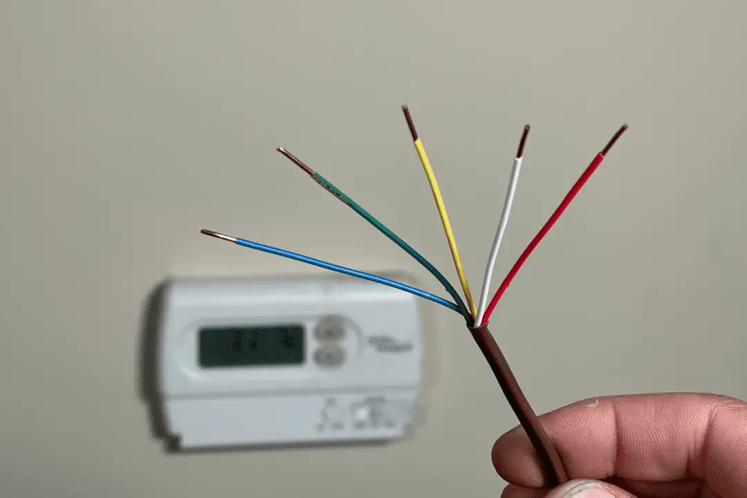
Upgrading a manual thermostat or an older, programmable one to a modern thermostat is a popular do-it-yourself project. Installing a smart thermostat always starts out simple enough; it can take as little as 30 minutes. Depending on the age and configuration of your existing thermostat, however, you can run into complications that can extend out the time needed for this type of installation.
Chief among these complications is the fact that the wiring in an existing system is lacking. Most smart thermostats require constant power; more power than can be provided by batteries. This is where the C-wire comes in. A missing “common” or C-wire that furnishes a constant power supply is perhaps the most common obstacle you’ll encounter when upgrading a smart thermostat.
As such, adding a missing C-wire when you’re installing a smart thermostat is what we’ll be addressing in today’s how-to article!
Adding a C-Wire When Installing a Smart Thermostat: Step by Step Guide
If your system is missing a C-wire, never fear! Nearly all residential heating and cooling systems in North America today can be modified to include all five wires you need to make a full system function. It’s easy to do once you understand how it works. By following the detailed steps in this how-to guide, you’ll find the obstacle of missing wires far from insurmountable.
We’ll start with an explanation of how thermostats work. After that, we’ll go over how to install a C-wire and your new smart thermostat in 3 easy steps.
Rather watch than read? Check out this 10-minute video.
DISCLAIMER: This video and description contain affiliate links, which means that if you click on one of the product links, I’ll receive a small commission.
Adding a C-Wire When Installing a Smart Thermostat: Supplies, Tools, and Costs
Supplies
- Thermostat Wire (18/5 – 50 feet)
- Electrical Tape
- Coaxial Cable Clips
- Cable Ties
Tools
Estimated Costs
A 50-foot precut length of 18/5 thermostat wire is readily available online and in most home centers for about $20 (as of January 2022). Other lengths are also available, and many home centers also offer the same product cut and sold by the linear foot, if significantly more or less is needed.
Adding a C-Wire When Installing a Smart Thermostat: Considerations Before You Begin
There are a few other things you may need to consider both before and after rewiring/replacing your thermostat(s):
- Newer smart thermostats often have a “footprint” that is much smaller than the ones they replace. When you remove the old thermostat you may find drywall damage, faded paint, or paint of a completely different color.
- As an alternative to paint/wall repairs, consider a base plate. Many thermostats have base plate options already available. Alternatively, check out our idea to create a base plate using a switch cover plate. It’s a very presentable solution that costs just a couple of dollars.
- This article discusses thermostats using/switching 24-volts A/C, the most common arrangement in North America. While this is considered low voltage and is generally safe to work on, any thermostats connected directly to line/mains voltage (120 volts or higher) can be dangerous and should only be serviced by those with sufficient electrical knowledge and training.
How Thermostats Work
In order to understand what the C-wire is and why it’s important, it’s necessary to understand how a thermostat works. In its most basic form, every thermostat is a switch, physically turning your heating or cooling on or off depending on the temperature you set.
For example, when heat is called for, the thermostat physically connects an always-on, incoming 24-volt A/C “hot” wire to a corresponding wire for heat. As long as the thermostat is calling for heat, it will remain on. Once the target temperature is reached, the thermostat will break the connection, turning the heat off.
Breaking the Color-Code of the Wires Inside a Modern Thermostat
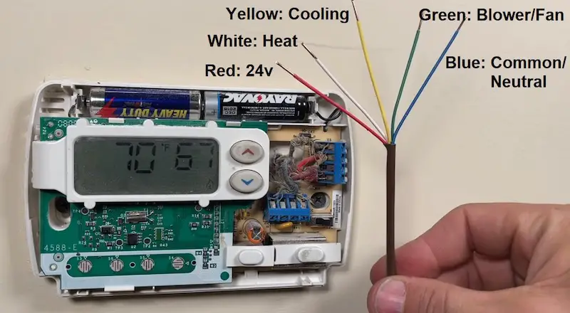
Note that there are no strict color codes for the wires inside your thermostat, so what you see in your case may vary. Generally speaking, the following are most commonly used in modern installations:
- Red = 24 volt A/C “hot” (“R” terminal)
- White = Connection path for heat (“W” terminal)
- Yellow = Connection path for cooling (“Y” terminal)
- Green = Connection path for blower fan (“G” terminal)
- Blue = “Common” neutral for always-on power (“C” terminal)
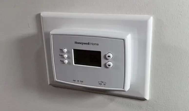
Typical Wiring Configurations in Older Thermostats
In older manual thermostats, and even in some newer battery-operated programmable ones, we only needed three wires: the red power wire, the white wire for heat and/or the yellow wire for cooling. There was no “common” or “C” neutral wire. In this arrangement, there is no way for a new smart thermostat to access always-on power for its operation. A C-wire will need to be added in order for a smart thermostat to work.
Step 1: Assess Existing Wiring
We’ll begin by examining the low voltage wiring at both the thermostat and the system control board. We’re going to make note of the wire colors and the terminal to which each is connected. If you’re extremely lucky, you may find the common wire already there, tucked away behind the thermostat and at the control board, simply needing to be connected to the “C” terminal at either end.
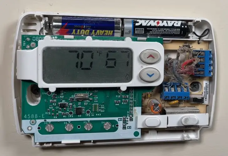
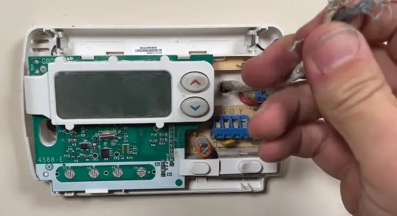
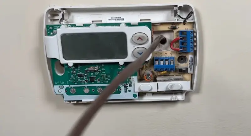
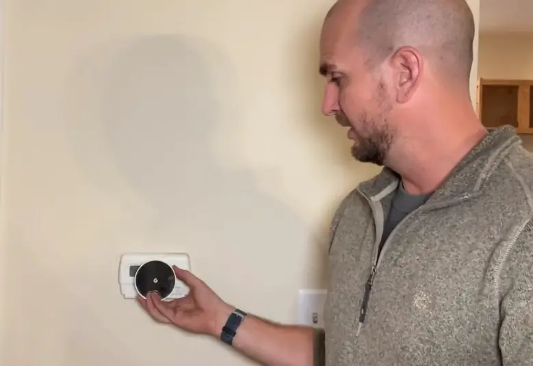
Let’s pop off the cover of the thermostat to see what we’re working with. This is a moment of truth, when it will become clear whether the project is going to be easy or more involved.
In our case, the blue wire is connected to the Y terminal. In a modern setup, this is where the yellow wire would be connected to control cooling. This means that the blue wire is not being used as a common wire in this old thermostat.
We can confirm this by tracing the wire from the thermostat to the control board in the basement.
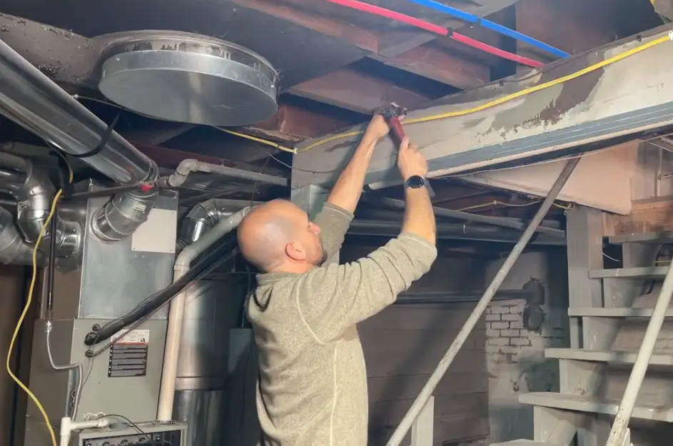
To access the control board, remove the panel on the lower part of your heating unit.
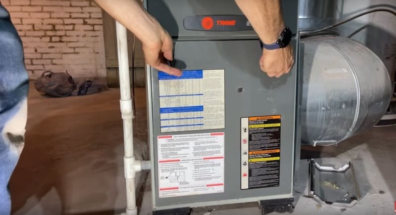
With the panel off, you’ll see the control panel right on the outside of the blower fan motor.
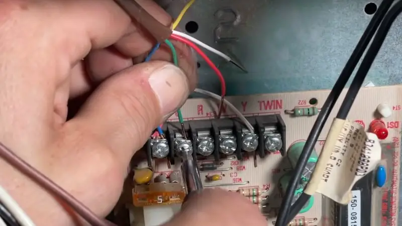
You can also see that the blue wire is connected to the Y terminal.
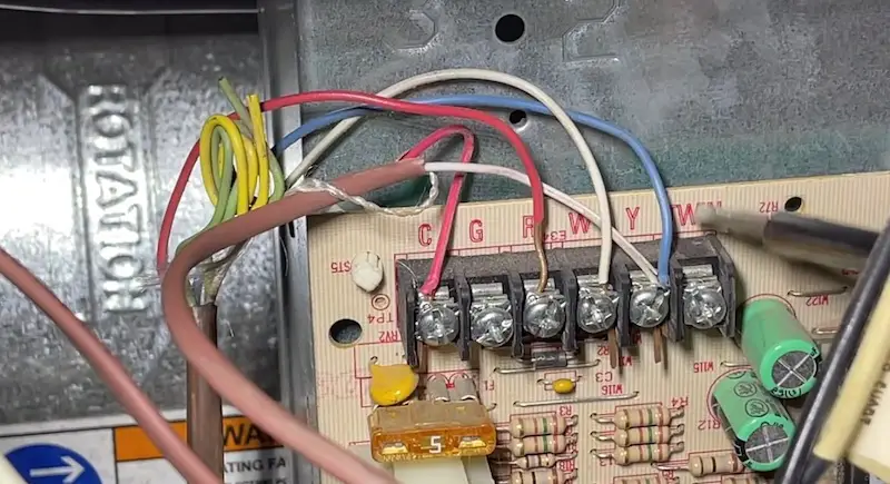
You may see other wires connected to the control board that don’t come from the thermostat and these should be left alone. For example, in this system, a separate two-conductor wire connects the control board to the A/C condenser outside. These connections might control other things, such as zone valves in a hot water heating system. We won’t be addressing those in this tutorial.
Even though a portion of this wiring already has five conductors, it’s spliced into a three-wire cable for the portion leading to the thermostat.
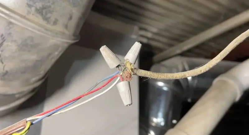
The best way to fix this setup is to replace the entire run of wire with new 18/5 (18-gauge, 5-conductor) thermostat wire, eliminating the splice. To make things easier, we’ll use the old wiring to pull the new through the wall.
Pro Tip: Remember that there are many possible system and wiring combinations; yours may vary from that shown here. For example, a heating-only system using hot water or steam baseboards/radiators would have neither a “G” (blower fan) nor a “Y” (A/C cooling) wire.
Step 2: Run New Wiring
Our first step before running new wiring is to verify that the existing wiring is loose in the wall.
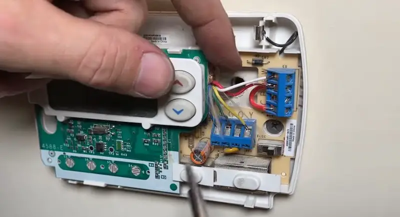
With the power off, loosen the screw terminals to detach the wiring in the thermostat.
Tug gently on the wiring. If it pulls out freely with a lot of play you can be sure the wires are not secured to the studs inside the wall. You might want to do this tug-test where the wire emerges in the basement as well.
Now, at the thermostat, we’re going to attach the new cable to the old and tape it smooth so that the new can be pulled down through the wall to the basement. Use two conductors from the old wiring and two from the cable, looping them around each other and then twisting them together.
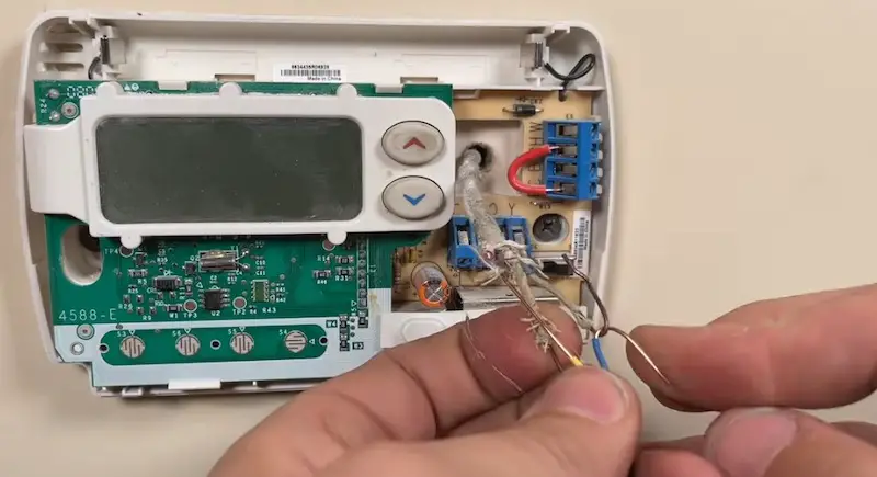
The remaining wires should be clipped down to their sheaths and the connection double-wrapped with electrical tape to minimize sharp edges and friction.
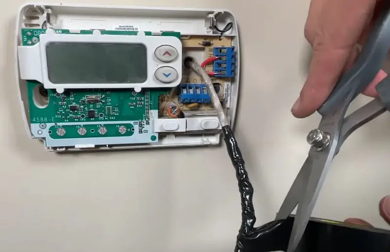
Carefully feed the new wire into the wall.
Once the wire is traveling freely, go down into the basement and gently pull down as much of it as you need. This step is easier and faster with two people, but it can be accomplished by one person alone.
Be sure to leave a small amount of extra wire at both ends in order to accommodate future repairs.
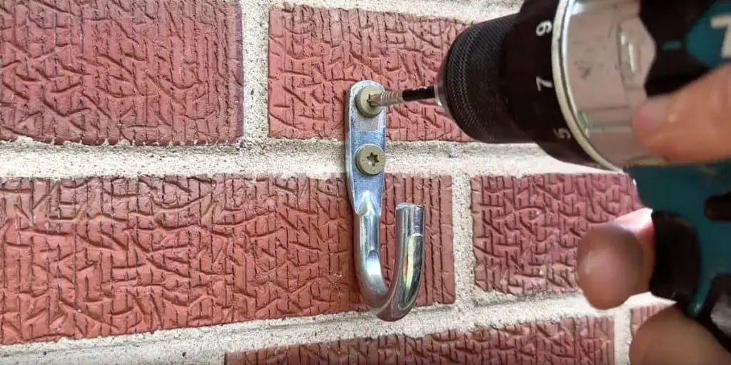
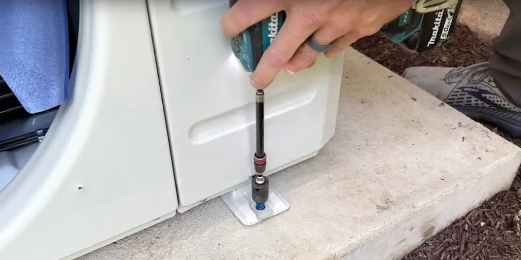
Route the wiring along beams and joists, securing the wire with coaxial clips and cable ties as appropriate.
Step 3: Remake the Connections
With the power still off, remove the old wiring from the control board of the heating unit by loosening the screw terminals.
With your wire strippers, strip approximately 1/2-inch from the end of each wire.
Connect each wire to the appropriate terminal on the control board:
- Blue to “C”
- Green to “G”
- Red to “R”
- White to “W”
- Yellow to “Y.”
Remember that, depending on your system type, you might not need all these wires, and that’s okay.
Back at the thermostat, ensure that all of the old wiring has been removed.
Repeat the same steps to connect the new wiring to the thermostat (strip the wires to about a half-inch and make the appropriate terminal connections). This applies whether you are installing a new, smart thermostat or troubleshooting/updating the wiring in an existing thermostat.
Finishing Touches
As we mentioned in the “Considerations Before You Begin” section, a new smart thermostat can be smaller than what’s currently on your wall.
A simple solution to this problem is adding a base plate. These sometimes come already made but you can create your own, quite simply and economically, out of a switch cover plate.
Adding a C-Wire When Installing a Smart Thermostat: Conclusion
Adding that missing C-wire is simple enough that it shouldn’t hold you back from installing a smart thermostat. which can greatly improve energy efficiency. Just take the time to understand what type of system(s) you have and pay careful attention to the steps we’ve described for an easy and successful result.
Got other home repair projects to tackle?
Check out my favorite type of flooring Glue-Down Vinyl Plank. This is a bullet-proof flooring solution especially for rentals, high-traffic areas, kitchens, and bathrooms.