My Account
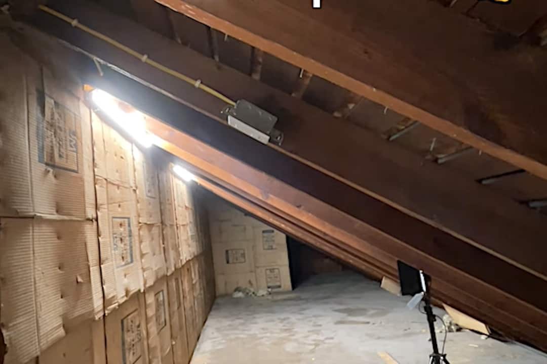
Got a utility space that could use some illumination? Today’s DIY project is how to install strip lighting with a motion sensor in an attic in order to make it more functional.
This process will also work in a garage, basement, or crawlspace — any place where you need a simple lighting fixture and don’t mind seeing the Romex cable running along your rafters or floor joists.
The subfloor in this attic is in good shape and there’s a ton of great storage space. The challenge with this home improvement project is that there is currently no lighting in the space. Fortunately, we have one little piece of 12/2 Romex sticking out of the wall near the top, so we do have a power source.
I’m going to install two 4-foot LED strip lights in this attic. They’re suitable here because they lay quite flat to the wall so you won’t bump your head on them. Simple lamp holders could work as well, depending on how your space is configured.
Installing LED Strip Lighting with Motion Sensor: Step-by-Step Guide
In this how-to guide, I’ll walk you through the steps to install LED strip lighting and a motion sensor switch in an attic space.
Of course, each person’s setup is going to be a little different, but the concepts are easily adaptable to other situations.
First, I’ll show you all the tools and components we’ll be using. Then, I’ll go over all the steps to install the LED utility lighting with motion sensor. I’m installing a simple, flat, strip lighting fixture that’s 4 feet long, somewhat similar in shape to an old-school fluorescent light.
My space is 24 feet long. I’m going to add two light fixtures, centering them at the 8′ and 16′ marks. I’ll also put a light switch near the door.
The switch has a motion sensor built into it, which means that you just open the door and the light comes on. When it doesn’t detect movement anymore, the lights turn off automatically, so you never have to worry about leaving the light on in the attic again.
The motion sensor is very handy in this sort of space, seeing as you typically have your hands full coming in or going out. A convenient feature is that you can set the time interval for switching off to suit the size and particulars of the space.
Let’s get started.
Rather watch than read? Check out this 13-minute video.
DISCLAIMER: This video and description contain affiliate links, which means that if you click on one of the product links, I’ll receive a small commission.
How to Install Utility Lighting with Motion Sensor: Supplies and Tools
Supplies
- LED Strip Lights
- 12/2 Romex (25′)
- 12/3 Romex (25′)
- 1 Gang Electrical Box
- Motion Sensor Light Switch
- 3/8″ clamps
- Romex Plastic Staples
- Wago 221 Kit
Tools
- Makita Cordless Drill Combo Kit
- 5/8″ Spade Bit
- Johnson Torpedo Level
- Klein Voltage Tester
- Milwaukee Wire Strippers
- Utility Knife
- Milwaukee ECX #1 Screwdriver
- Impact Driver with a Robertson bit
How to Install Utility Lighting with Motion Sensor: Review of Tools and Components
Let’s review the parts and components I’m going to be using to install this lighting with motion sensor in my attic space.
Here’s my electrical box that I’ll be mounting on one of the rafters. I already have the ground pigtail installed since it’s a metal box.
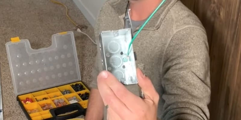
I’ll be using ⅜-inch clamps for strain relief and to make sure there are no edges that can cut the Romex as it enters the light fixtures or the electrical box.
This circuit is 20-amps. It has a 20-amp breaker at the electrical panel. We’ll be using both 12/2 and 12/3 Romex for the wiring on this project.
Instead of wire nuts, I’m using Wago 221 lever nuts. If you’ve seen any of my other videos, you know these are my preferred connector. I use them on pretty much all electrical projects now, I think they’re very convenient and the efficiency of the connection is better than traditional wire nuts.
I’ll be using both 3-wire and 2-wire lever nuts for this lighting install.
As far as tools, I have my drill with a ⅝-inch spade bit for drilling holes in the rafter to run the Romex through and help protect it. You could use an auger bit for this if you wanted.
I have my impact driver with a Robertson bit because I’ll be sinking a few screws.
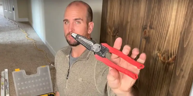
Here are my wire strippers, which are a hybrid tool by Milwaukee. They’re both wire strippers and linesman’s pliers (or Klein’s) in one. Very handy. These are my go-to now.
Lastly, I have a utility knife for cutting the Romex and a screwdriver. I use a combo screwdriver, an ECX #1 by Milwaukee. It has a Robertson square head and also a flathead built into one. Super convenient for electrical work.
Let’s jump into the attic and start putting this together.
Mounting the Light Fixture Casing and Electrical Box
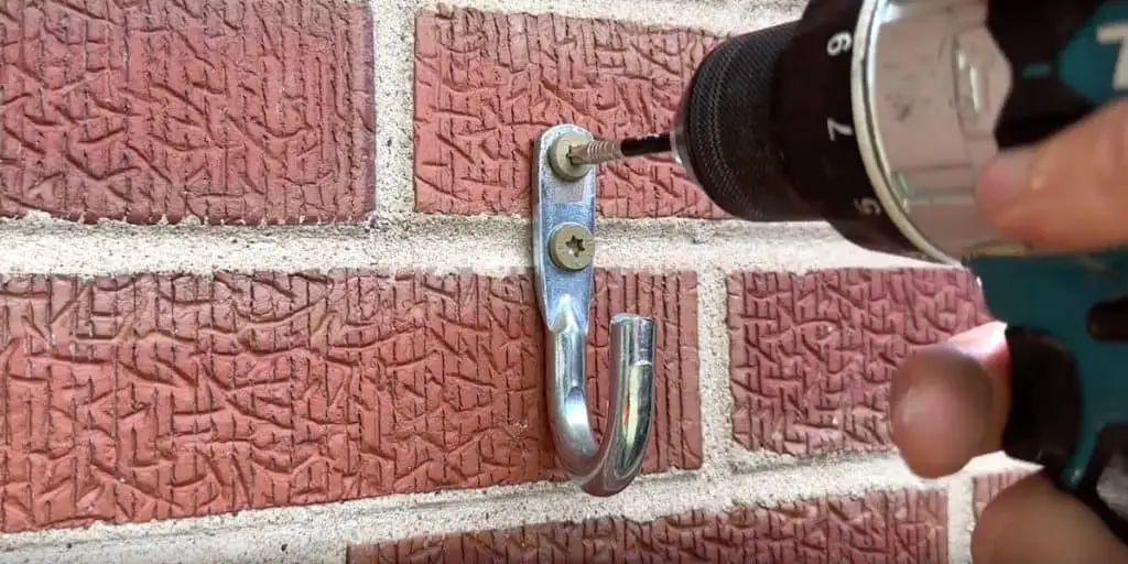
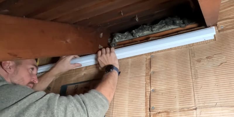
To get the most solid support, I want to mount the casing of the strip lights to studs.
I’ll first sink a screw to secure one end of the light housing to a stud. In this attic, I can easily see where the studs are because the top sheet of the insulation is riveted to them. You might need to use a stud finder depending on your setup.
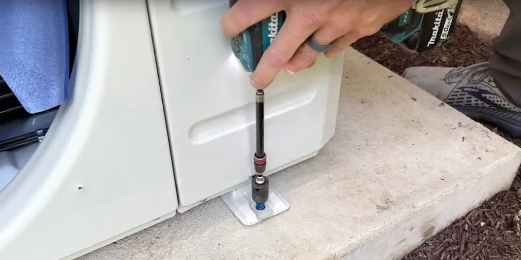
Then, on the other end of the housing, I’ll mark the location where I’m going to drill a new hole that lines up with a stud, after making sure the light fixture is level by using my Torpedo level.
After drilling the new hole, I’ll sink a screw to finish mounting the housing of the light fixture to the wall.
I’ll do the same thing downstream with my second fixture.
Next, I’ll mount the electrical box that will hold the motion-detecting light switch. I’m locating it near the entrance to the attic so that when I open the door, it will turn on the lights automatically.
Running the Romex
Creating a Pathway for the Romex
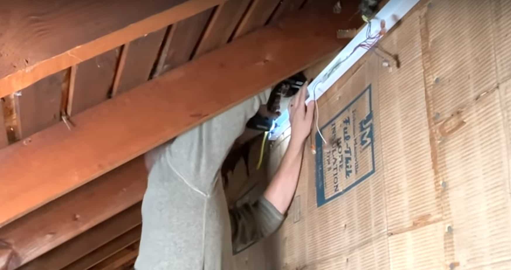
With my drill and a ⅝-inch spade bit, I’m going to drill some holes through the rafters as needed to carry the Romex.
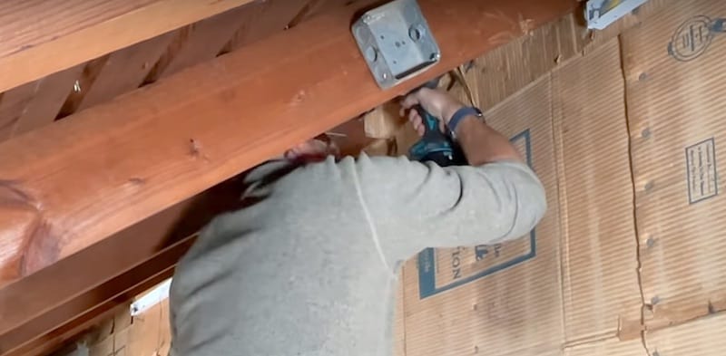
I’ve drilled the holes fairly close to where the rafter meets the wall and about 2 inches from the bottom side of the plank.
Stringing and Cutting the Romex
SAFETY NOTE: Before starting to do any wiring, I need to switch off the power to my circuit at the breaker box. Then, I’m going to confirm with a non-contact voltage tester that the Romex I’m about to work with is not live. It’s always a good idea to test the voltage tester on a live source before you test your Romex, just to be sure the voltage tester is functioning properly.
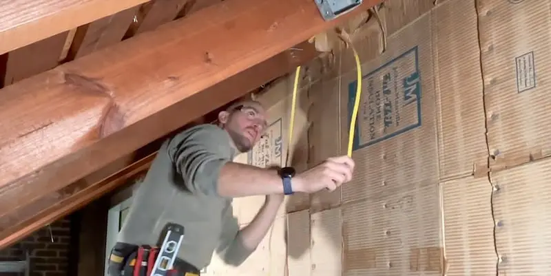
My power source coming out of the wall is a piece of 12/2 Romex. I’ll feed the 12/2 into the first light fixture, which is furthest away from the door.
Next step is to run some 12/3 Romex between the fixtures. I need the third wire to act as an additional hot that will pass back power from the switch.
I’ll first pass the 12/3 Romex through the holes in the rafters.
Before pressing the Romex into the ⅜-inch clamps inside the housing of the second light fixture, I’ll cut it to length. Obviously, I want to be a bit generous when cutting the Romex. I’ll trim it more precisely in a bit.
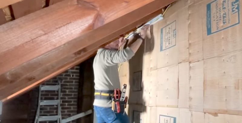
From the switch, I’ll run a piece of 12/2 to the second fixture and then cut it, again leaving a little extra length. I’ll also secure it to the rafter with clips, which I’ll place in the middle of the rafter, away from the decking of the roof and away from the bottom of the rafter.
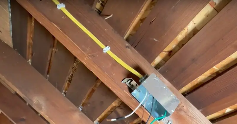
You don’t want to put the Romex too close to the top of the rafter. In the event of roofing repairs, the Romex shouldn’t be so close to the decking as to catch a nail (you can see a nice one protruding from the roof decking in the photo).
All that’s left to do for this step of running the Romex is tightening down all the clamps and then cutting the Romex down more precisely.
Here’s a little summary for easy reference regarding the Romex:
- Incoming power to first fixture: 12/2 Romex
- First fixture to second: 12/3 Romex
- Second fixture to switch: 12/2 Romex
Connecting the Romex to the Fixtures and Switch
Now to make the connections at each of the light fixtures and the switch.
SAFETY NOTE: I’ve already switched off the power at the breaker box and confirmed with a non-contact voltage tester that the wires I’m about to work with are not live.
Quick recap of the situation: At the first lighting strip, furthest away from the entrance, we have power coming in through our 12/2 Romex and going downstream to the second lighting strip through our 12/3.
Wiring Up the First Light Fixture
Wiring up the neutrals and grounds of this light fixture is very straightforward.
I have already placed two 3-wire Wago 221 lever nuts here. One Wago is connecting the neutral wire from the junction box of the lighting instrument to our incoming power source (the Romex coming from the wall), and the other Wago connects the ground wires.
Now I’ll just complete the neutral connection by inserting the neutral wire of the 12/3 Romex (that’s running between the light fixtures) into the last chamber of the lever nut containing the other neutrals. Then I’ll do the same with the ground wire of the 12/3. Once they’re connected, I’ll tuck the wires into the fixture housing.
Now let’s talk about how to tie together the hot wires, one set to take power all the way to the switch and the other set to bring power to the lights and turn them on when the motion sensor of the switch kicks in.
Bringing Power to the Switch
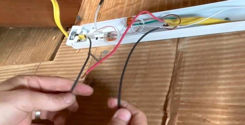
The black wire in the 12/2 Romex coming from the wall is my hot wire, my incoming power. For now, I’m going to connect that to the black hot wire in the 12/3 Romex going to the second light fixture. (Ultimately, this will bring power all the way to the switch, once I connect the last piece of Romex from the second fixture to the switch.)
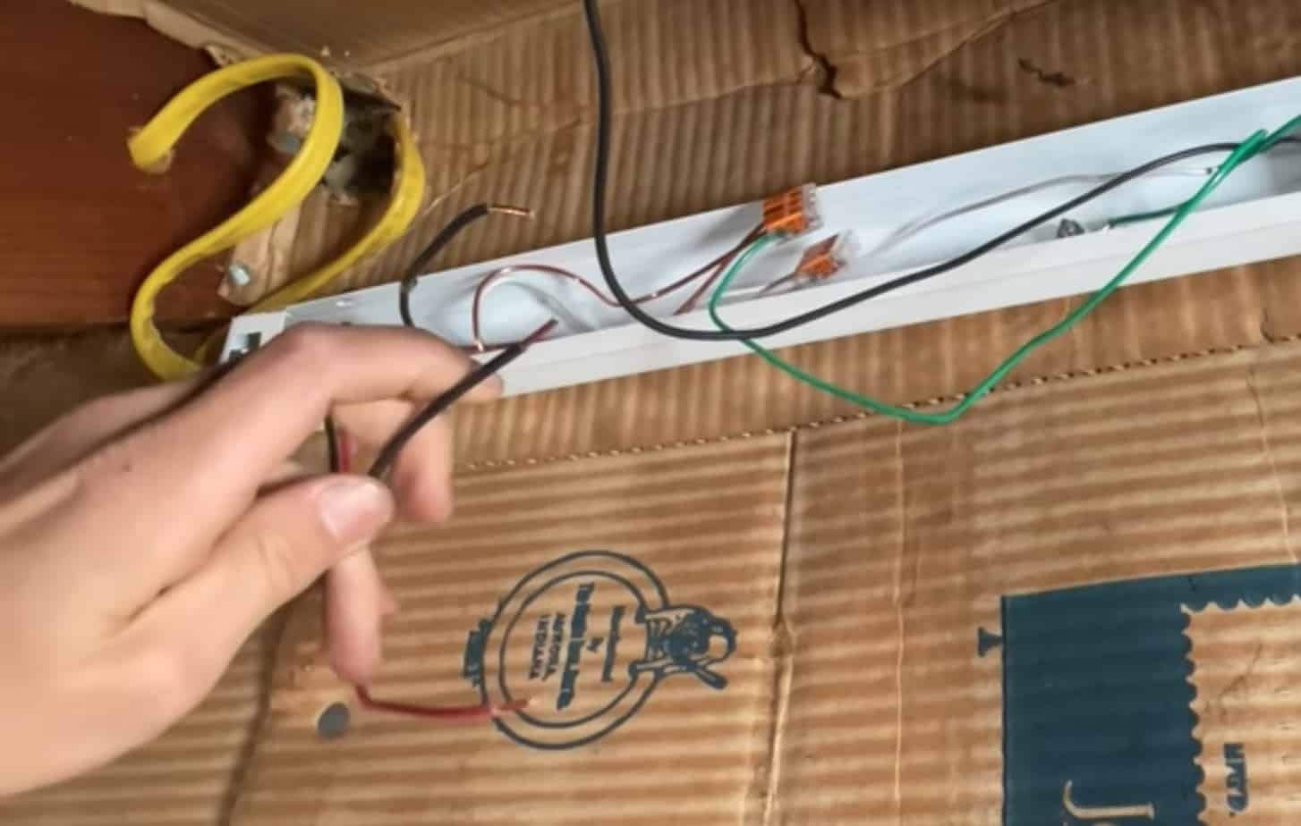
I’ll use a 2-pin Wago to connect these hots and pass the power through.
Bringing Power to the Fixtures
Now to start the connection of wires that will come from the switch to turn the lights on and off.
The red wire in the Romex 12/3 is what’s going to bring power to the lighting fixture itself, so I’ll connect that to the black hot wire coming from the junction box of the light with a Wago 2-pin.
Remember, with the Wagos you can see that your wires are fully seated on the bus bar but you can also do a pull test just to make sure they are securely clamped.
A handy feature of this light fixture is this quick disconnect that you can use to easily remove and reconnect the front LED panel/cover to do wiring such as this or service the fixture.
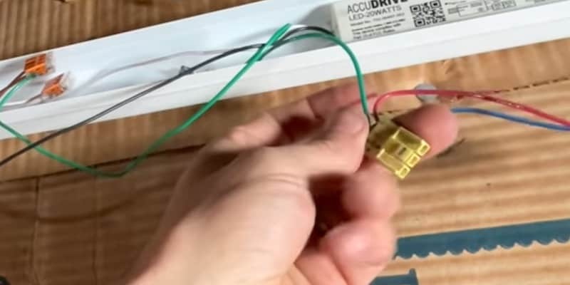
Let’s get all our wires tucked into the housing, reconnect the LED panel, and snap it into place.
Wiring Up the Second Light Fixture
Recap: At the second light fixture, we have 12/2 Romex coming from the switch and we have 12/3 Romex coming from the first fixture, which is connected to my power source.
Again, the neutrals and the grounds are straightforward. Refer to the previous section for details on how I connected those.
Now to complete the wiring that will bring power to the switch.
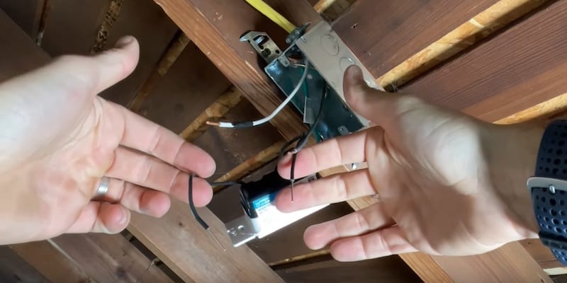
I’m going to connect the black hot wire of the 12/3 Romex with the black hot wire of the 12/2 leading to my switch.
This completes the power supply, bringing power all the way to the switch from where the power enters the space. (Remember that previously we connected the hots of the 12/2 coming from the wall with the 12/3 between the fixtures.)
Our last wiring step is to connect the switch that will turn our lights on and off.
You can see that I’ve marked the neutral wire of the 12/2 coming from the switch with black electrical tape.
The tape indicates that the neutral wire is no longer being used as a neutral. Now it’s going to serve as a “switched hot” to pass power when the motion detector of the switch kicks in. The motion sensor serves to break or complete a circuit, which then reroutes the current.
NOTE: In my area, what I’ve done here meets code. You should check the electrical code in your area to see if a neutral is required in this configuration for a switch box. If so, you’d need to use a piece of Romex 12/3 between the switch to the fixture.
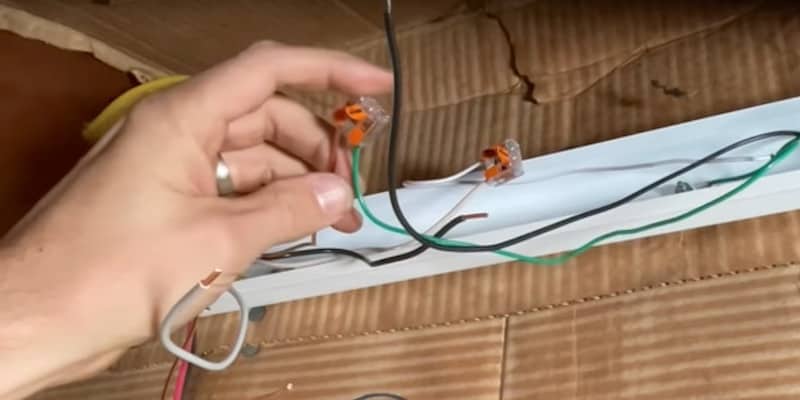
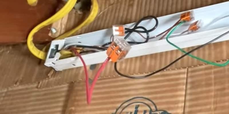
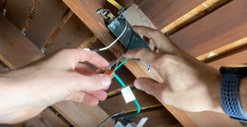
With a Wago 3-pin lever nut I’m going to connect:
- the black hot wire from the light fixture closest to switch
- the neutral white wire marked with black tape (now my hot wire coming from the switch)
- the red wire of the 12/3 leading back to the fixture furthest away from switch
Wiring Up the Light Switch
We’re at the last part of the wiring before we test things out, which is installing this Lutron motion-detecting light switch. Wiring the switch is very easy.
The Ground Wires of the Switch
I already have the ground for the switch in a 3-wire Wago lever nut. I’m going to add the ground wire from the 12/2 Romex to it, and then the ground wire that’s grounding our electrical box.
Once those are all secured in the connector, I’ll tuck all the ground wires back up into the box.
The Hot Wires of the Switch
My switch has two black hot wires.
I’m going to connect one of these hots from the switch to the black hot wire coming from my Romex. The other I’ll connect to the “switched” hot (the white neutral I’ve marked with black electrical tape that’s going to provide our on/off functionality.)
Very simple, we’ll just be putting 2-wire Wagos on these. I’ll do a pull test to make sure everything’s secure.
Now to tuck the hot wires back into the box and mount the switch on the box.
How to Install Utility Lighting with Motion Sensor: Testing and Conclusion
Now to test out our newly-installed LED strip lighting with motion sensor.

Nice! It works as expected. When I open the door to the attic, the lights come on.
Well, that’s it for this project!
You can see that adding some lighting makes a huge difference in the functionality of the attic as a storage space. Now I can come in here with a ton of stuff in my arms or take a ton of stuff out, and the motion sensor is going to detect me and turn the lights on when I enter and turn them off when I leave after the pre-programmed five minutes.
Other Electrical-Related Repairs
To see another electrical-related DIY repair, namely how to fix an outlet that won’t hold a plug, please watch our YouTube video or read the step-by-step guide.
To Leave Comments and Questions
If you would do things differently, please leave a comment under the YouTube video. I welcome your opinions. You can post questions there as well. I do check them on a daily basis and am happy to help out.
Don’t forget to subscribe to our channel as we have weekly videos coming out to help you with your everyday home repairs.
We’ll catch you on the next one! Take care.