My Account
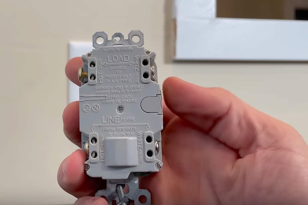
If you’re working with a GFCI outlet for the first time or if it’s been a while since you installed one, the most common point of confusion is the difference between the “line” and “load” terminals when you have multiple sets of wires coming into the box.
Fortunately, the confusion is quite simple to unwind: the “line” terminals are for power coming into your electrical box and the “load” terminals are for carrying that power plus GFCI protection to outlets further downstream.
How to Wire a GFCI Outlet: Step-by-Step Guide
In this tutorial, I’ll walk you through how to safely identify which wires are which in your electrical box and then I’ll show you where they connect to your GFCI outlet.
We’ll go step by step through how to connect the wires using my electrical box as an example, not only to provide power to this 15-amp GFCI outlet but also to provide power and GFCI protection to outlets further down the line (“downstream”).
Electrical work can be a little daunting at first, but with best practices for safety, some basic knowledge, and careful attention, you can be wired up correctly and safely the first time around.
Let’s get started!
Rather watch than read? Check out this 5-minute video.
How to Wire a GFCI Outlet: Supplies and Tools
Supplies
Tools
- Phillips-head screwdriver
- Needle-nose pliers
- Non-contact voltage tester
- Klein Tools MM600 multimeter
- Klein outlet tester (not used here but will come in handy later for detecting problems)
Do You Need a Ground Wire with a GFCI?
Before we jump into testing and wiring our GFCI, let’s talk about ground wires for a sec.
One of the most common misconceptions when it comes to GFCI outlets is that you need a ground wire. You actually don’t need a ground for the GFCI to operate properly but it is recommended.
For example, in an old house with no grounds running to the electrical boxes, I replaced the ungrounded, two-prong outlets with GFCI three-prong outlets. In my area, that meets code.
Even without a ground, the GFCI will still trip and protect you if the electrical current starts to surge or stray (in other words, if a ground fault is detected.) Instead of directing deviant current to the ground, the GFCI interrupts the flow of electricity. Either way, you will prevent electrical shock that could result from a ground fault.
Inside the Electrical Box: Identifying the Wires
If you are installing a GFCI for the first time and you have multiple sets of wires in your electrical box, it can be a little confusing, but it really isn’t complicated once you know how to use some simple tools.
I’ve removed my GFCI outlet to show you how to identify which wires go to which terminals. Have no fear, we’ll make sure you’re wired up safely and correctly the first time.
SAFETY NOTE: I turned the power off at the breaker box and confirmed with my non-contact voltage tester that there’s no power at the outlet before disassembling it.
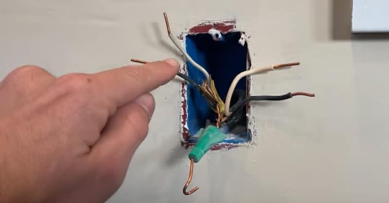
You see that there are two sets of wires in my electrical box, each set with one hot, one neutral, and one ground wire.
Using a Voltage Tester to Find the Incoming Power
Now I’ll flip the breaker on and get out both my non-contact voltage tester and my multimeter.
The non-contact voltage tester will tell me if there’s power present in the wire. The multimeter will give me a reading of the volts in the circuit between the hot and ground wires. With the info from these tests, I’ll be able to confirm which wires are bringing power into the box.
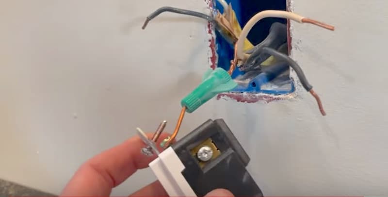
You’ll notice that I’ve attached Wago clips to the black hot wire in both sets of wires.
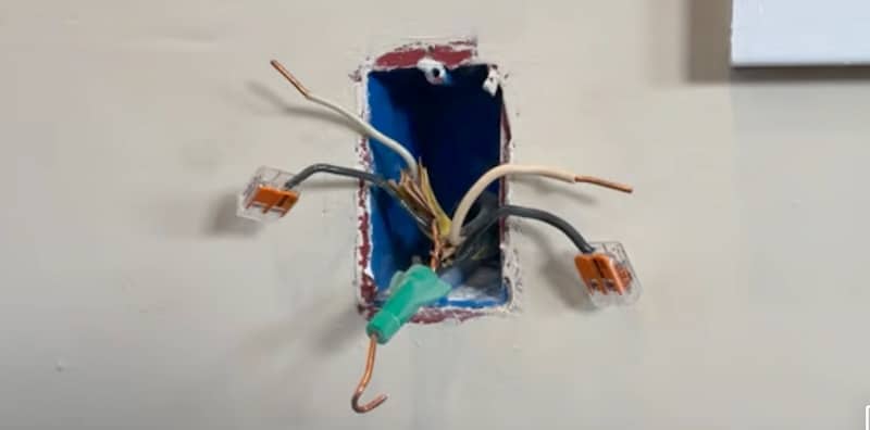
A Wago is a lever nut, which is a better alternative to wire nuts for splicing wires together. It’s a connector in the form of a clip that provides a secure and efficient wiring connection and is ideal for DIYers. It also makes electrical work go faster.
Now for the tests.
To get my readings on these wires, I’ll first bring the non-contact voltage tester close to the wires.
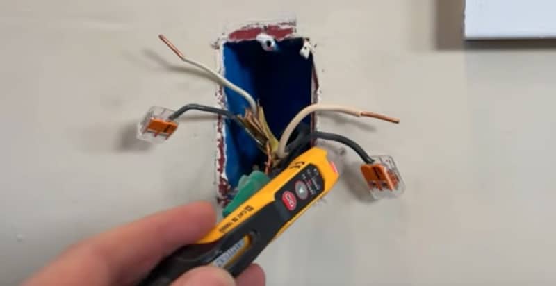
The voltage tester lights up red when I put it near the black hot wire on the right, which means there’s power. This is the set of wires I need to connect to the “line” terminals of my GFCI.
Having identified the set of wires on the right as incoming power, it’s obvious that the set on the left will be connected to the “load” side. The wires from the “load” terminals will provide GFCI protection to the standard outlet connected downstream.
Verifying Voltage of the “Line” Terminals
Now let’s get a voltage reading on our incoming power.
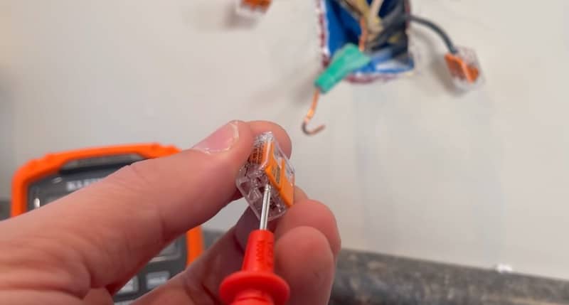
These Wago 221 connectors — the 2-wire, the 3-wire, and the 5-wire — all have a test port under one of the levers.
Place your probe underneath the lever and you’ll get a connection to the busbar inside the Wago. The busbar is the collection point for all the wires in the connector and the source of readings for diagnostics or troubleshooting the circuit.
To get our voltage reading, we’ll set our multimeter to voltage, then connect the black probe up to the ground wire and our red probe to the test port of the Wago containing the hot wire.
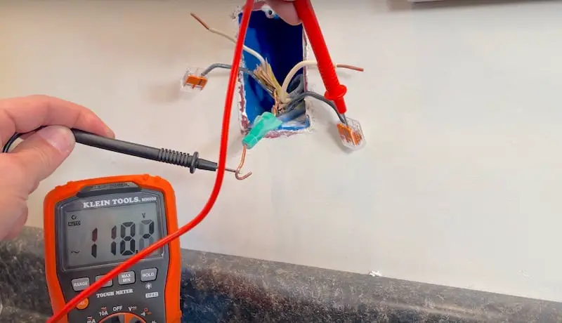
And there’s our reading — 118 volts!
We’re getting the voltage expected from this 120-volt circuit. Now I’m confident that I’ve identified my “line” wires.
The “Load” Terminals
If this were a brand new GFCI, there would probably be yellow tape over these “load” terminals.
Remember, you’d use the “load” terminals if you had wires going to other downstream outlets, standard receptacles that you want to protect with GFCI. This is the setup I have here.
How to Wire a GFCI Outlet: Summary of the Terminal Connections
On a GFCI outlet, black hot wires connect to the gold (brass) terminals and white neutral wires connect to the silver terminals. Black to gold; white to silver.
The wires bringing power into the box will connect to the “line” terminals and the wires going to a downstream outlet will connect to the “load” terminals, as follows:
- The wires bringing power into the box:
- Black hot wire —> gold “line” terminal
- White neutral wire —> silver “line” terminal
- The wires connecting to a downstream outlet:
- Black hot wire —> gold “load” terminal
- White neutral wire —> silver “load” terminal
How to Wire a GFCI Outlet: Connecting the Wires
SAFETY NOTE: Before connecting any wires, I’m going to turn off the power and verify with my voltage tester that there is no current.
Connecting the Ground Wire
I have a ground available so I’m going to first connect that to its terminal on the bottom of the GFCI receptacle.
It’s always best practice to connect the ground if you have one. You might need some needle-nose pliers to help you get the ground wire tightly around the screw in the counterclockwise direction.
Connecting the Hot and Neutral Wires, Mounting the Outlet
With the ground wire connected, I’ll now connect the hot and neutral wires in my electrical box to the terminals on the GFCI by inserting the end of each wire into the appropriate slot (as specified in the “Summary of the Terminal Connections” section above) and tightening the screws with a screwdriver.
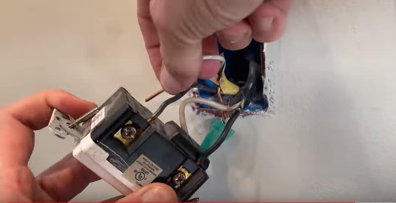
With all the wires securely connected, I’ll remount the outlet by screwing it back onto the wall brackets and reattaching the faceplate.
How to Wire a GFCI Outlet: Conclusion
That’s it, we’re done!
Hopefully you now have a clear understanding of “line” and “load” on a GFCI outlet and you’re feeling confident about identifying and correctly connecting the wires in your electrical box.
Other GFCI-Related Repairs
Got old 2-prong outlets you want to replace? Check out our YouTube video to learn how to replace an old 2-prong outlet with a 3-prong GFCI step by step.